The other one with 12V which is used to power the three-phase bridge and therefore the BLDC motor. In this project we need two power sources, the first one with 5V and used to power the microcontroller. In the circuit diagram above the 3 phases are named: Phase A, Phase B and Phase C. Note that all grounded terminals are connected together.Īs known the brushless motors are 3-phase motors. Sensorless BLDC motor controller using PIC18F4550 microcontroller circuit:Ĭircuit schematic diagram is shown below. PIC MCU programmer (PICkit 3, PICkit 4 …).
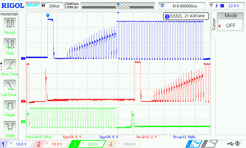
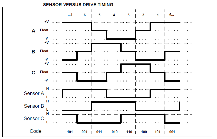
3 x IR2101 (or IR2101S) gate driver IC – datasheet.6 x 06N03LA N-type mosfet (or equivalent) – datasheet.PIC18F4550 microcontroller -> datasheet.The sensorless BLDC motor control technique is based on the BEMF (Back Electromotive Force) produced in the stator windings.įor more details about the sensorless BLDC motor and how to control it, see the following project:īrushless DC motor control with PIC16F887 microcontroller First the brushless dc motor is a 3-phase motor comes in two main types: sensored and sensorless.

